Author Topic: Pong TV game - A Scratch build Scale project  (Read 121817 times)

level42

  • ArcadeLifeStyler'
  • ***
  • Posts: 13555
  • Ridderkerk, arcade capital of Europe !
    • View Profile
    • Arcade 42
Re: Pong TV game - An upcomming Scratch build project
« Reply #30 on: May 21, 2012, 11:14:27 PM »
Ahhhhh, look at that nice Hong Kong craftsmanship. Look at the wires being soldered to one side of the resistors.....then again, Wells-Garnder did the same stuff....

I would go lazy on it this time....just find the spot where the diodes hook up together and you've got your video (ignore that NTSC label, it can't be NTSC (or PAL) there yet, it is still unmodulated there !).

You can even pick-up the audio and lead it to the TV input. Depends which one has the better speaker ;) ;) ;)

Etienne MacGyver

  • ArcadeLifeStyler'
  • ***
  • Posts: 7611
  • The Netherlands
    • View Profile
Re: Pong TV game - An upcomming Scratch build project
« Reply #31 on: May 21, 2012, 11:21:52 PM »
The guy that i took the schematics of, states that the AY-3-5800 is pal and the AY-3-5800 1 is the NTSC variant of the chip..

Quote
Note that the AY-3-8500 is the European version that outputs PAL, the AY-3-8500-1 is the U.S. version that outputs NTSC.

http://www.electronixandmore.com/project/pongman/index.html

I dont know it, but however it may be, i got the european version of the chip and a pal TV so it must work together  8)

Good point about the speaker, i am curious how the original cabinet has it, did they also wire it to the tv speaker, or if not , where is the speaker located in the cabinet ?

level42

  • ArcadeLifeStyler'
  • ***
  • Posts: 13555
  • Ridderkerk, arcade capital of Europe !
    • View Profile
    • Arcade 42
Re: Pong TV game - An upcomming Scratch build project
« Reply #32 on: May 21, 2012, 11:25:07 PM »
Mmmm, I stand corrected. Normally NTSC/PAL is used for the "transmitted" HF signal. I bet both would work on a modern TV, but whatever...

My guess-in-the-dark would be that they used the TV for sound because it has an amp and a speaker inside already and cost was everything ;)

PunkRockCaveman

  • Member
  • **
  • Posts: 399
    • View Profile
Re: Pong TV game - An upcomming Scratch build project
« Reply #33 on: May 21, 2012, 11:26:16 PM »
I would go for the quick win here, too. These consoles and also the chip isn't very scare. So go ahead, find the composite-spot and solder a cable onto that. Ah ... yes, that is the implementation I did ;)

Etienne MacGyver

  • ArcadeLifeStyler'
  • ***
  • Posts: 7611
  • The Netherlands
    • View Profile
Re: Pong TV game - An upcomming Scratch build project
« Reply #34 on: May 21, 2012, 11:27:56 PM »
Question then is, what resistor i need to add to the audio signal, since its directly hooked up to the speaker, or do you think i can straight feed it into the audio in at the AV port ?

I dont want to "overmodulate" it since i guess its already a bit amplified.

@jorg;

Thanks, i think i will try that then..
but not today, its now time for me to go to the couch and put the feet up  :D
« Last Edit: May 21, 2012, 11:31:03 PM by Etienne »

Etienne MacGyver

  • ArcadeLifeStyler'
  • ***
  • Posts: 7611
  • The Netherlands
    • View Profile
Re: Pong TV game - An upcomming Scratch build project
« Reply #35 on: May 22, 2012, 07:40:04 PM »
The AY-3-8500 uses seperate pins for each part of the playfield and the sync. there are four playfield/ball/score display pins and one sync that you can combine via diodes. here is the pinout of the chip:


I'm pretty sure they did exactly that in your console. Just follow the pins and you will find the combined signal before it goes into the rf-modulator ;)

Just took a look at the wires that come from the option switches and "hardwired" the ones that needed connection.

Looking at the pins after folowing the traces, it is exactly what it says (ofcourse)..

I hardwired 8 (auto serve), 5 (ball angle)
7 (ball speed) and 13 (paddle size) where "switch in open position"  ;D  so did not need anything connected to them.

later i will remove the game selector switch and hardwire 20 (tennis)

what i dont get is that the manufacturer bridged pin 3 and 27 together  ???

« Last Edit: May 22, 2012, 07:52:22 PM by Etienne »

Etienne MacGyver

  • ArcadeLifeStyler'
  • ***
  • Posts: 7611
  • The Netherlands
    • View Profile
Re: Pong TV game - An upcomming Scratch build project
« Reply #36 on: May 24, 2012, 08:03:59 PM »
Back on this,

I removed all switches and hardwired the necessary connections so the PCB only plays pong with dedicated settings for balspeed, angle, batsize and automatic serving mode.

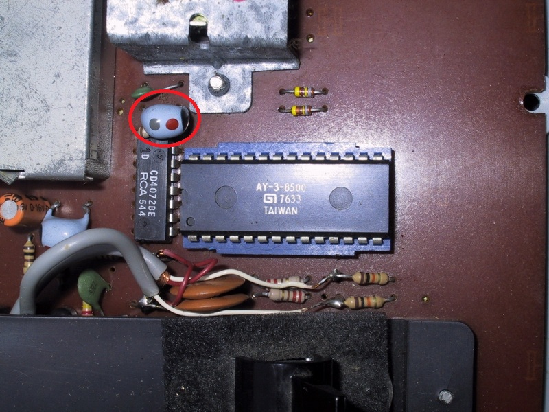
Then i folowed the advice to folow the traces for IC pins 6, 9, 10 & 24 and find the point where they come together after the diodes in this schematic:


Hmm, no diodes in my search....  they end up in another IC..  a CD4072BE ???

okay.. hmm and now ??

.
..
...
....
.....


Ofcourse !


The outputs from the pong chip go to these inputs of the CD4072BE:

6 --> 9
9 --> 10
10 --> 11
11 --> 12

I found the datasheet of the CD4072BE and that looks like this:


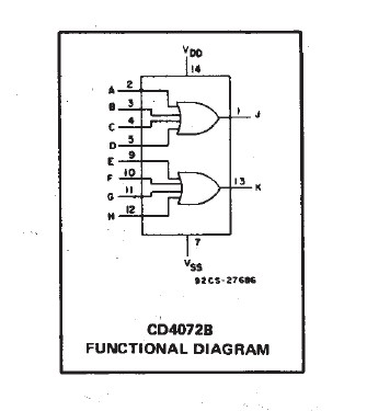
Now, i dont have any knowledge of these chips, but i see that pins 9, 10, 11 & 12 go in, and at the end of that thing i only see 1 pin come out..
Could it be that this chip is just 2 sets of diodes in a IC housing ?

I have no idea, but as the great C64 Game, i have only one rule...  ;D


So i hooked up the wire that goes to the AV in on the TV at pin 13 from the CD4072BE..

Are we ready for a testrun ??   :P


Hmm, i have some image, but it looks like i have a major sync problem....  :?

So i followed the trace comming from pin 13 of the CD4072BE and it goes into a "big blue blob thing"

I think its a ceramic capacitor or something simular ?


Anyway, i moved the wire from pin 13 to the other side of the "Blob" and tried again...

See for yourself where i stand now..
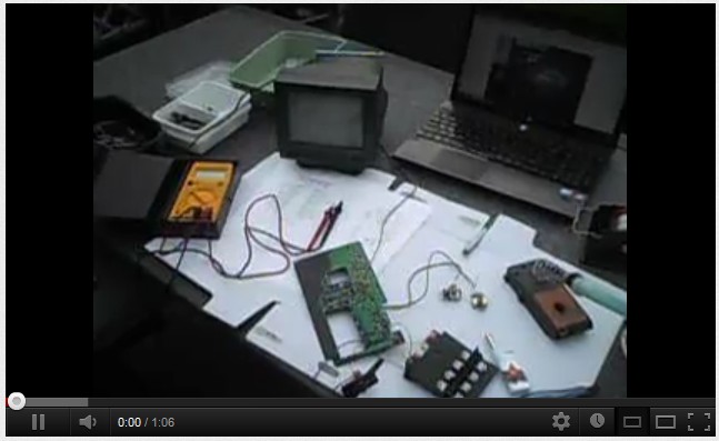
Click pic..
« Last Edit: May 25, 2012, 09:35:54 PM by Etienne »

level42

  • ArcadeLifeStyler'
  • ***
  • Posts: 13555
  • Ridderkerk, arcade capital of Europe !
    • View Profile
    • Arcade 42
Re: Pong TV game - An upcomming Scratch build project
« Reply #37 on: May 24, 2012, 08:32:36 PM »
Hahahah, yessssss !!!

Can't tell by the video if it looks (much) better than through RF though, but it has to be :)

That chip is a dual OR gate.

The function is very simple: There or two OR gates that have 4 inputs and one output.

The top OR gate has pins 2,3,4 and 5 as inputs and 1 as output. The second...well you can understand.

If ANY of the inputs so pin 2 OR 3 OR 4 OR 5 is high, the output will be high too.
ONLY if ALL inputs are low, then the output will be low too.

So, in this application, it's simply "adding" the signals from the AY-3-8500-1 chip together, much like the diode solution does. I think the chip is a more decent design, the diodes is a "rough" solution that does the same thing...

It's that simple. Don't touch that chip with your bare hands, it's a CMOS version which gets much easier damaged by static than TTL.
It can also handle a broader range of voltages, which is probably why they chose it...

Isn't it simply brilliant that by plugging in that 3,5mm jack it automatically switches to AV input, perfect for your application ! :)
« Last Edit: May 24, 2012, 08:36:06 PM by Level42 »

Etienne MacGyver

  • ArcadeLifeStyler'
  • ***
  • Posts: 7611
  • The Netherlands
    • View Profile
Re: Pong TV game - An upcomming Scratch build project
« Reply #38 on: May 24, 2012, 08:48:06 PM »
Yes, and even better, i hooked up the sound also to that same A/V connector.

But i think i need a little pre amp for it, the sounds are almost not hearable and the volume is at its maximum as you could see in the vid.

And indeed, the picture is much higher quality than the RF.
Also its very dificult to do the finetuning with that tv..

Anyway , Mission acomplished !!!  :spaceace:  

« Last Edit: May 24, 2012, 09:04:19 PM by Etienne »

level42

  • ArcadeLifeStyler'
  • ***
  • Posts: 13555
  • Ridderkerk, arcade capital of Europe !
    • View Profile
    • Arcade 42
Re: Pong TV game - An upcomming Scratch build project
« Reply #39 on: May 24, 2012, 08:51:39 PM »
Glad you put in the little bit of extra effort, and I'm sure you are too now :)

Did the game play the audio through the TV when you hooked it up through RF and was the volume OK then ?

level42

  • ArcadeLifeStyler'
  • ***
  • Posts: 13555
  • Ridderkerk, arcade capital of Europe !
    • View Profile
    • Arcade 42
Re: Pong TV game - An upcomming Scratch build project
« Reply #40 on: May 24, 2012, 08:54:00 PM »
Wait a minute, did you pick up the audio directly from the AY chip ? I bet there's a simple amp on the board somewhere. On your pics I can't see under the controls section though...can you make one that reveals the entire board ?

Etienne MacGyver

  • ArcadeLifeStyler'
  • ***
  • Posts: 7611
  • The Netherlands
    • View Profile
Re: Pong TV game - An upcomming Scratch build project
« Reply #41 on: May 24, 2012, 09:02:53 PM »
I used the wire that was on the speaker, which is after a bunch of resistors and transistors

So yes, there is a little preamp there, that must be.
Let me see if i can take a macro pic of the board..

BRB.

And yes, i am happy i did put in the extra effort, not so much for the quality of the image (well, that too ofcourse), but more to see if i could pull it off  :wink:
« Last Edit: May 24, 2012, 09:05:58 PM by Etienne »

level42

  • ArcadeLifeStyler'
  • ***
  • Posts: 13555
  • Ridderkerk, arcade capital of Europe !
    • View Profile
    • Arcade 42
Re: Pong TV game - An upcomming Scratch build project
« Reply #42 on: May 24, 2012, 09:07:36 PM »
Mmmm strange, you would assume that the output to the speaker would be _more_ than enough as an audio level input for that jack input because it can drive an entire speaker.

Check if one of the speaker wires is connected directly to ground (the ground you use for the video). If that is so, than it should sound fine.

If it's not, then I can understand it because it will get only a minimal level. I don't think it's a good idea to hook up one of the speaker wires together with the (video) ground though, you might blow up something....

level42

  • ArcadeLifeStyler'
  • ***
  • Posts: 13555
  • Ridderkerk, arcade capital of Europe !
    • View Profile
    • Arcade 42
Re: Pong TV game - An upcomming Scratch build project
« Reply #43 on: May 24, 2012, 10:01:02 PM »
By the way, great weather to work in the garden/yard right ? ;)

I'm trying to get my "set-up" pool up....Of course, as every year, there are leaks in the inflatable ring...lot's of fun for dad this pool !
Replaced all the old patches (3 already) and just found a new hole. Fixed it but every time have to wait at least 30 minutes to let the patch dry before inflating again and then wait to see if it stays ok....

The next month it is maintenance, scooping up all the leafs and stuff, vacuuming the floor, keeping the chloride up to level, check the water quality, covering it every night, check the filter in the pump.....yep, gotta love it :)

(OK it IS nice to jump in to cool off a bit after a really hot day :) ) And the kids love it :)

The good thing: I don't put it up every year. I don't know why, but sometimes I really don't feel like doing it, and then every year when I do NOT put it up, the weather sucks during the summer....last year I didn't put it up and the summer sucked....just like all the other times.

So...this means we're getting a great summer this year ;)

OK back on topic :D

Etienne MacGyver

  • ArcadeLifeStyler'
  • ***
  • Posts: 7611
  • The Netherlands
    • View Profile
Re: Pong TV game - An upcomming Scratch build project
« Reply #44 on: May 25, 2012, 01:12:25 PM »
Cool! , i did the same thing yesterday, only is a little less profi pool that i have  ;D


The speaker ground is hooked up to the same ground as the ground for the video signal.

Here some close ups of the board:
I tried to read the text on the transistors, i dont know if i got it exactly right, it is really small text, and i did not have my magnifier glass at hand..


The RF output was connected here, and that ground was indeed not the main ground.


Anyway, ill try to hook up the old speaker again and see if i get the old level back, or discover that i have indeed a problem..