Author Topic: WG 6100 repair logs  (Read 44875 times)

anunaki

  • ArcadeLifeStyler'
  • ***
  • Posts: 1432
    • View Profile
Re: WG 6100 repair logs
« Reply #30 on: March 19, 2014, 10:18:11 PM »
nice find

are you going to use the freeze spray to find the component that fails cold and works warmed up?

level42

  • ArcadeLifeStyler'
  • ***
  • Posts: 13555
  • Ridderkerk, arcade capital of Europe !
    • View Profile
    • Arcade 42
Re: WG 6100 repair logs
« Reply #31 on: March 19, 2014, 10:34:04 PM »
Yup that's the idea ! :)

Etienne MacGyver

  • ArcadeLifeStyler'
  • ***
  • Posts: 7611
  • The Netherlands
    • View Profile
Re: WG 6100 repair logs
« Reply #32 on: March 20, 2014, 08:12:40 AM »
hmm interesting

i never seen something like this, but who am i  ;D

Anyway, what happens to that spot where the stuff is missing if you let a game running ?

is it missing like a circle there that is growing to completion or do you have lines there too ?

will be dificult to fill that area i think, because its vector ?

Laszo

  • ArcadeLifeStyler'
  • ***
  • Posts: 993
  • Building
    • View Profile
Re: WG 6100 repair logs
« Reply #33 on: March 22, 2014, 06:51:14 AM »
Man, that really sucks, I wonder what they paid their employees  :roll:

smarty

  • Jr. Member
  • *
  • Posts: 99
  • Hampshire, UK.
    • View Profile
    • Jumpnfire.com
Re: WG 6100 repair logs
« Reply #34 on: March 22, 2014, 02:30:15 PM »
Here's a repair log from a W&G6100 which I worked through recently, Level42 said it was OK to post it in this thread,I posted this on UKVAC so you may have seen it already, but its good to share tech info to make it easier for us to get them fixed when they break.

////////////////POST 1
I've got a 6100 that failed, B+ Video is not sitting at 180VDC, some background to the fault...

The monitor did work when I picked up the cab, I could never get the game board (tempest) full size on the screen using the board pots, after being on for a while I started getting what looked like horizontal collapse from the top to centre(if the monitor was in horizontal position) I recapped the Deflection board, recapped the HV board and fitted an LV2000, the monitor still worked. One day after being turned on and playable, the display went dead.

What I've found so far...

On P900 connector I had 27/-27VDC on the correct pins but only 25V on B+ Video which should have been 180VDC.
* I found R920 Open circuit. REPLACED.
* I found R918 (HV adjust pot OC) replaced. Cheers Phil!
* All other resistors tested in spec according to the schematics.
* All transistors were removed and tested. All were fine except Q905 a 2N6557? Base/Emitter was open circuit in both directions using diode test on my multimeter.

I replaced this tonight with a MJE15030G which I think is a current equivalent? Can someone please confirm... I understand the the pinout is different and modded it accordingly to suit the HV board positioning.

http://www.actionpinball.com/tech/wmshv.htm (bottom half of the page) documents the difference and I did the leg re-routing and used some heatshrink to insulate the pin that routed behind the
base and collector.

Time to power up again...

P900 connector was sitting at 150VDC which seemed like a good start without having adjusted the HV pot. This voltage slowly started to decrease and within 30 seconds smoke was coming from the HV board! Doh! Q905 which I had just replaced was burning hot. Visual inspection showed that R917 has burnt, I removed it from the board and it was reading dead short, so I replaced it and checked over Q905 and confirmed the pinout was correct for the new transistor, I removed it from the board and tested it again and I read as expected.

 I thought I'd fire it up to see what would happen and no smoke this time, but the VideoB+ was sitting at 75VDC, adjusting the HV pot made no difference to the voltage.

The 6100 FAQ says that if R917 smokes, Q905 is inserted backwards...

I will have another MJE15030G delivered tomorrow but don't want to put it in and watch things go up in smoke again.

Can someone please confirm what a current day Q905 (2N6557?) replacement can be used, and any ideas what may have gone wrong?

////////////////POST 2

Well I fitted an MJ340 tonight and bang, the screen came to life... MJE15030 not man enough for the job!

Not 100% but it is working. I can only get 15.KV measured at the anode 160VDC on the Video B+. I have the spot killer on too, this was originally always off started coming on recently, I need to look at what axis it is and check the measurements from the gameboard. If I turn the brightness up on the monitor I can see a line left-right with the game playing (monitor in vertical position)
---------------------
`                       `
`                       `
`                       `
`                       `
` --line-here----`
`                       `
`                       `
`                       `
--------------------

I'm think this is horizontal collapse? Someone please confirm. I'm sure its now a board fault, but as I'm still not able to get full HV I've got a bit more work to be getting on with. Monitor and Gameboard :( ... TBC...

////////////////POST 3

To Follow this up and close out the low B+ issue Big smile the following took place over the last week or so...

Nad sent me a few of the Zener diodes with some parts for the AVG board (thats for another thread!) once fitted I still had B+ limited to 160VDC. Time for a sanity check, I reprinted out the HV circuit and went through marking off the components, values and associated known voltages. When I got to R917 the nut finally cracked!

When I swapped it after I smoked it fitting an under rated Q905, I replaced it with a 3K3 resistor this should have been a 3.3Ohm resistor. Well after swapping that out tonight, B+ is now fully adjustable and sitting happily at 180VDC.

FIXED!
To Summarise the parts needed to fix my Low HV fault: (not including the parts I caused to fail)
R920 Open circuit. REPLACED.
R918 (HV pot) Open circuit. REPLACED.
Q905 Open circuit. (Base/Emitter fault) REPLACED with an MJE340
555 timer. Unknown fault but I tried the original IC tonight that I had replaced and B+ jumped back to 25VDC. Needless to say I didn't leave the monitor turned on for more that a few seconds...

I've now got some deflection issues on the monitor, I'll write up a post about that tomorrow.
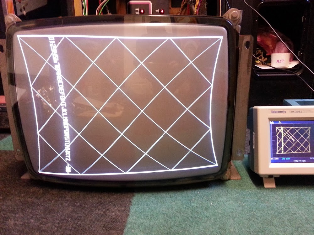
////////////////POST 4
Following on from the Low HV problem, I now connected the monitor back up to the cab loom and was greeted with the images below:


Some sort of deflection issue? The game looks and plays fine on my scope.

Well I took the deflection board our and removed all the transistors and all read well out of circuit except for the last one! Q604 an MPS-U07 in the Y section was open circuit in both directions across B-E and B-C. I've ordered some ZTX653 replacements and some clip on heat sinks so I'll let you know the outcome early next week.

////////////////POST 5
Progress


New MJE15030 fitted at Q604 with pins swapped to fit the deflection board requirements. 'X' board adjustments work fine, but on the 'Y' side I cannot make the image any larger than what is shown. Looks like Q603 is next in line for replacing with an MJE15031 once thats done and hopefully working I think I'll shotgun Q703/4 with new transistors to be on the safe side.

*EDIT* Re pincushion effect on the 6100. Is there any adjustment for it? The right side of my screen image seems to display it pretty badly, not sure if thats a function of the deflection not working properly yet or another game/monitor board I need to investigate.

////////////////POST 6
Just to confirm my thinking earlier... The 1st photo below shows the original fault once HV was sorted, the second shows what changing Q604 fixed. (Y axis issue) So my next fault is the X axis counterpart. Someone pls confirm, have I got the X/Y axis labelled the correct in the second photo for the monitor, I think its correct from my findings so far. Thanks.


////////////////POST 7
OK so replacing the the transistors in the 'X' section hasn't sorted the folding of the image as it did with the 'y'axis, but at least it confirms that the transistors MJE15030/31/32/33 are suitable swap outs.

I have today found the D701 in the 'X' section is short circuit its a 1N914B. I put a 1N4148 in I had spare and screen size is fully adjustable. Ordered 20 1N914B's  and will swap them when they get here. I'm making some adjustments to colour bias and gains and then I'll post a photo. So far so good!

////////////////POST 8
Right, so with diode D701 replaced from the deflection board I now get a full size image and screen size position if fully adjustable.

FIXED
To summarise the parts needed to fix the deflection issue:
Q604 an MPS-U07 in the X section (Monitor in landscape position) was open circuit in both directions across B-E and B-C. Replaced with an MJE15030 (MJE15032 will also work)
D701 (1N914B) diode short circuit. Part of the Y deflection circuit. Temporarily replaced with a 1N4148.

Something that got me confused whilst looking into the X/Y issues were that the gameboard adjusters for X and Y position/size refer to the monitor being in the 'vertical' position as in fitted in the cab whereas the monitor manual talk of X/Y in term of it being mounted in horizontal position. This might be a useful tip for anyone reading this in the future looking for 6100 help.

Here's a couple of images, unfortunately I think I have some sort of board fault as the image is smaller on one side (right) of the screen. This is seen on my scope so it can't be to do with the monitor.

Closing in on the fault, I've pretty much tested all the other parts in the circuit and this is hopefully the final faulty part.


////////////////POST 9
It turns out it was another MC1495 gone faulty on the AVG board. They're all socketed so wasn't too difficult to work out which one was bad by swapping them around. I swapped the bad one out and the image is now nice and square with very little if any pincushion. Job done! Well the EAROM is giving and error in test mode so no high scores are saving, need to have a look at that...


www.jumpnfire.com

MOST WANTED CABS:

level42

  • ArcadeLifeStyler'
  • ***
  • Posts: 13555
  • Ridderkerk, arcade capital of Europe !
    • View Profile
    • Arcade 42
Re: WG 6100 repair logs
« Reply #35 on: March 22, 2014, 05:53:55 PM »
Nice info Smarty !

Nice scope too.....I want to buy a Rigol sooooooon....


About MPSU07's: I'm selling them ! The original one's....I can also deliver MPSU56 which work just fine instead of MPSU57s.....

Laszo

  • ArcadeLifeStyler'
  • ***
  • Posts: 993
  • Building
    • View Profile
Re: WG 6100 repair logs
« Reply #36 on: March 24, 2014, 04:57:50 PM »
Thanks for the info. It is usefull info.... So you replaced most of that section of the board.

level42

  • ArcadeLifeStyler'
  • ***
  • Posts: 13555
  • Ridderkerk, arcade capital of Europe !
    • View Profile
    • Arcade 42
Re: WG 6100 repair logs
« Reply #37 on: March 24, 2014, 08:27:06 PM »
By the way I've never seen a vector monitor with such straight edges ! No pincushion at all !

Yeah....Tempest has pincushion correction on the game PCB.....they skipped it on SW. The manual says instead they compensated in the monitor's yoke but I don't buy it......ALL the SW games I have seen have inward pincushion on the left and right side.

Which remids me that I still have a kit to assemble that should actually fix this.....

smarty

  • Jr. Member
  • *
  • Posts: 99
  • Hampshire, UK.
    • View Profile
    • Jumpnfire.com
Re: WG 6100 repair logs
« Reply #38 on: March 25, 2014, 10:56:10 AM »
I borrowed the scope from work, but no one else has a use for it so it will stay at mine until someone needs it. :)

MPSU07/56 Good to know you have some, hopefully I wont need some any time soon.

Laszo, a quick overview of the whole monitor repair goes as follows:
Capkit (HV & Deflection board), LV2000, Couple of resistors, HV pot replaced, a few transistors replaced and a bad diode.

Re the pincushion or lack of it, yes it is a very 'square' image now which I'm happy with, Its just a shame my Tempest board has gone faulty so I'm currently not playing it... I love this hobby and 30+yr old electronics.
www.jumpnfire.com

MOST WANTED CABS:

Laszo

  • ArcadeLifeStyler'
  • ***
  • Posts: 993
  • Building
    • View Profile
Re: WG 6100 repair logs
« Reply #39 on: March 26, 2014, 07:43:20 AM »
I borrowed the scope from work, but no one else has a use for it so it will stay at mine until someone needs it. :)

MPSU07/56 Good to know you have some, hopefully I wont need some any time soon.

Laszo, a quick overview of the whole monitor repair goes as follows:
Capkit (HV & Deflection board), LV2000, Couple of resistors, HV pot replaced, a few transistors replaced and a bad diode.

Re the pincushion or lack of it, yes it is a very 'square' image now which I'm happy with, Its just a shame my Tempest board has gone faulty so I'm currently not playing it... I love this hobby and 30+yr old electronics.

Thanks, good to know for future fixes.

level42

  • ArcadeLifeStyler'
  • ***
  • Posts: 13555
  • Ridderkerk, arcade capital of Europe !
    • View Profile
    • Arcade 42
Re: WG 6100 repair logs
« Reply #40 on: April 04, 2014, 11:50:24 AM »
Well.....Bela's deflection board was repaired 100% back and sent back home to Hungary.

So I was back on getting Franck's 6100 back to Lofe FINALLY.

Last thing I had was a smoking resistor on the HV cage... Yet again, it was VERY valuable to be able to compare stuff with a good working HV board. I found one resistor to be open when it should be 2,2 Ohms. Also found that the bottle transistor on the cage was shorting to that cage...not good. Replaced the mica and silicon paste and reinstalled it, no more short.
Replaced the resistor and upgraded it to a 5W version at 3,6 Ohms as per the 6100 FAQ. While I had bought some of these I replaced the other 2,2 ohms resistor as well, also as suggested by the FAQ. once again, all transistors checked, all caps checked, I felt confident so installed it in Marco's working monitor and yessssssss running smoothly :):)

Next installed it on Franck's tube and frame and also used his deflection PCB. That was the one with the weird dark corner remember ?

Powered up, and to start with I noticed that the spot killer was on, despite having a picture. IIRC this was the board that had the wrong transistors in the deflection circuit so I suspected the 4 Mylar caps. Replaced them with 1 uF elco's (that's how we call electrolytic capacitors here) and BINGO ! No more spot killer led on, and no more weird black spot in the corner !

Next job was correcting the purity. Switched to res hash screen and purity was off. Loosened the yoke and managed to find the optimum location, rubber wedge mounted and yoke tightened. Still a bit of purity issue but was able to correct that with the purity rings. By the way, these rings were extremely tight , I could barely move them at all, was afraid to break the tabs.....I solved that by spraying some Teflon (PTFE) spray on the rings and the moving them, they moved like it was brand new after some turning :)

Further work was convergence, not too easy on this one, and it's not perfect but good enough for sure.

The res was weak on this monitor so I hooked up the Mueter rejuvenator and indeed the red gun is the weakest of the three but still in good condition so no rejuvenation necccesary.
To compensate I just upped the red color pots.

All in all a pretty nice picture, not as fresh looking as Marco's but very acceptable for sure.

Now there is just one issue left....I can't adjust the focus well enough. Turning the pot is not "instant" the focus change lags behind the turning of the knob, this is not normal. Also sometimes it "jumps" into and out of focus. Already checked the wire to the focus pot, was OK. Maybe it's the pin on the neckboard or the CRT socket, will check those soon. If not, it might be the pot itself and then I am afraid we'll have to order a new flyback.....

To be continued :)

level42

  • ArcadeLifeStyler'
  • ***
  • Posts: 13555
  • Ridderkerk, arcade capital of Europe !
    • View Profile
    • Arcade 42
Re: WG 6100 repair logs
« Reply #41 on: April 04, 2014, 11:51:02 AM »
One more picture...

Etienne MacGyver

  • ArcadeLifeStyler'
  • ***
  • Posts: 7611
  • The Netherlands
    • View Profile
Re: WG 6100 repair logs
« Reply #42 on: April 04, 2014, 07:33:21 PM »
SWEET !  :spaceace: :spaceace: :spaceace:

level42

  • ArcadeLifeStyler'
  • ***
  • Posts: 13555
  • Ridderkerk, arcade capital of Europe !
    • View Profile
    • Arcade 42
Re: WG 6100 repair logs
« Reply #43 on: April 05, 2014, 01:35:00 AM »
Always nice to see your enthusiastic replies Etienne, at least one person reads and enjoys these write-ups.

I will stubbornly continue, as I see it as my personal log for reference in the future in the cloud :D

Just had another look at the neck board and man-o-man....

The wires running to the board, some of them really felt like they could break from the solderings any moment. When I wiggled some one actually did. So I re-stripped all of them and desoldered all of them.
Next I looked at the focus wire which runs to the CRT socket. Popped open the plastic cover and the poor thing was "hanging on" with just a single strand of the wire !!! I touched it and pulled it ever so slightly and it broke loose.....
So fixed that too. Too late to test now...tomorrow we will see if this is fixed too. If so, we can throw it in a box and ship it to La France ;)

Laszo

  • ArcadeLifeStyler'
  • ***
  • Posts: 993
  • Building
    • View Profile
Re: WG 6100 repair logs
« Reply #44 on: April 05, 2014, 06:46:44 AM »
We are so impressed... That we have totally fallen silent  :o :o :o :o


WELL DONE MR. LEVEL 42  ;D  ;D