okay, its simple;
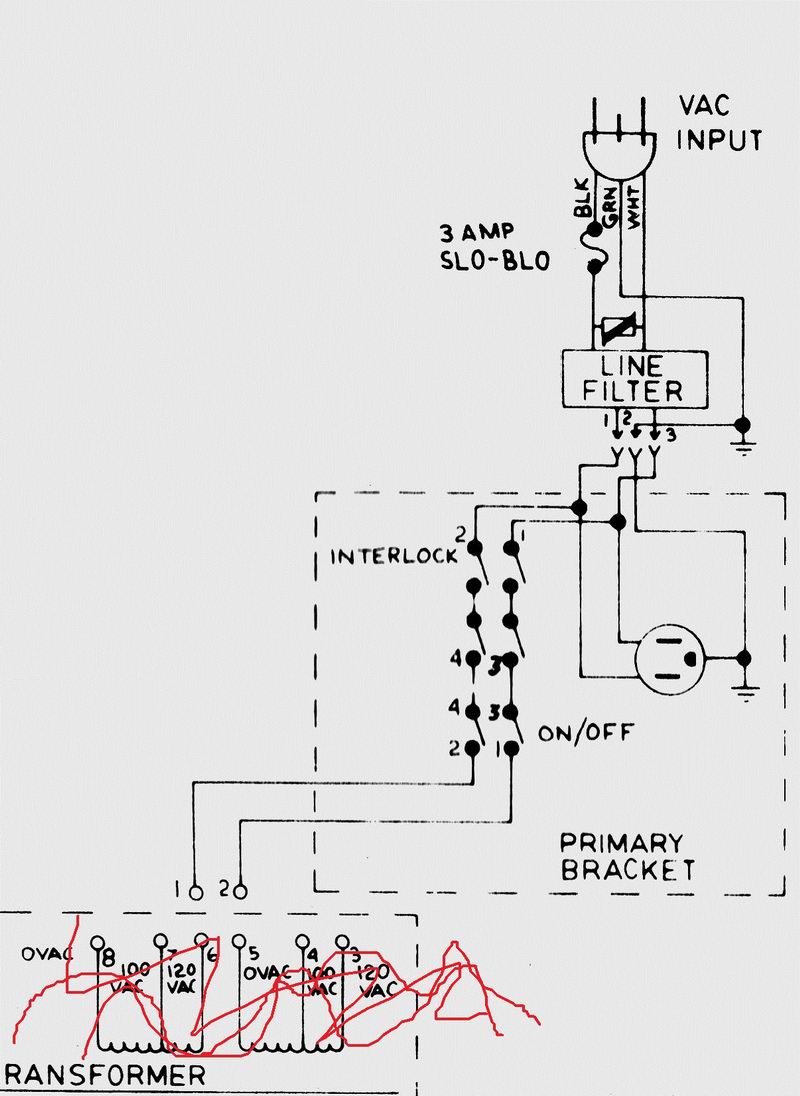
here the part of the wire-ing diagram that you need:
you see that the mains runs through the interlock switches and then to the powerswitch to end at point 1 & 2 that go to the transformer (which you dont have, so thats where the switcher will come)

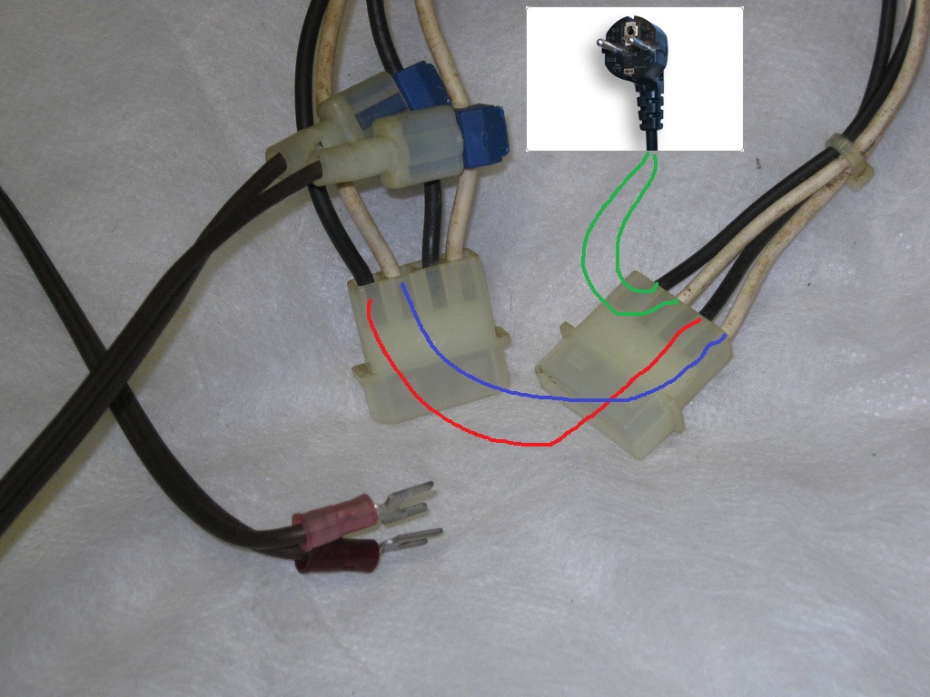
i would say wire it like this, because you dont have the brackets:
green lines is the mains comming from your wallsocket (plug)
it goes into the connector to the on/off switch and comes back in the same connector at the other pins (C & D )
connect those to the other plug (red and blue line) (G & H )
they go through the interlock switches and come back as the other pair (which is tapped to go to the switcher)

you can just cut the connectors off and solder them together and isolate them with shrink tube or electrical tape or something like that.
the only difference in your cable that i can see is that they changed the sequence of the interuptors, (the tapped part that goes to the switcher comes from the interlock switches, and not like in the schematics from the powerswitch..)
is everything clear now ?
EDIT:I almost forgot the stepdown converter...
so cut also the tapped wires off and go to the stepdown converter from there..