ok, time to work on the wiring problem! i hope to solve it with the help of you guys ...


 be warned, this is going to be a long posting with a lot of pictures and if you really want to help me, you'd better grab something to drink first and take your time going through it ...
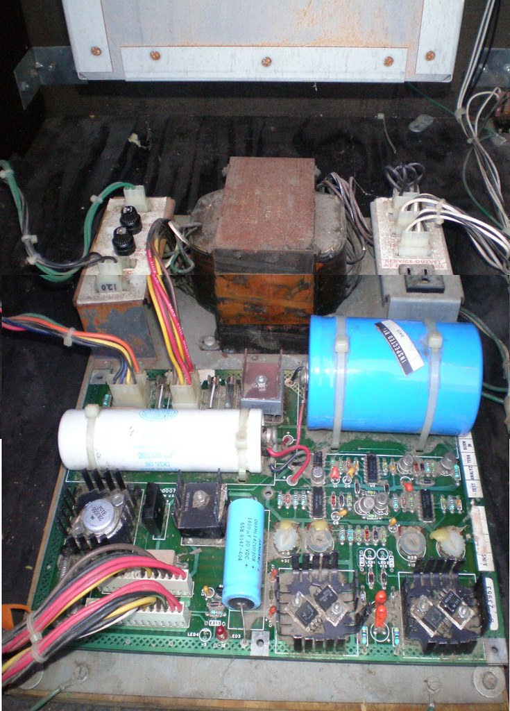
as i've stated before, i have a wiring harness which has been modified to be used with a switching power supply. i don't have any part of the original power supply at all, but in order to show you the differences / hacks i'm going to include pictures of the original wiring.
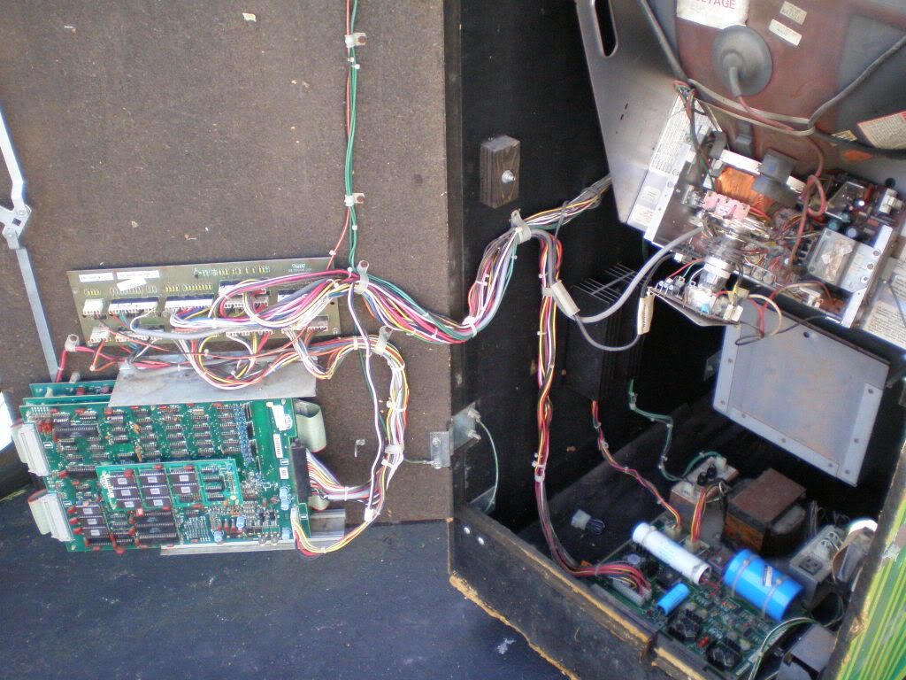
let's start with a general overview of a jungle king cabinet:
on the left you can see the pcb on top of which sits the filter board (can anyone tell me what the function of it is? and don't just tell me "it filters something out" please

). inside, at the bottom of the cabinet, you can see the original power supply and on the cabinet's left side hangs a strange black "box" of which i have no idea at all what it is (a data recorder like the ones used on airplanes perhaps)?

and here's the original power supply (note that i had to stitch two pictures together to show you the entire thing. not perfect, but it'll do)
i don't have that original power supply, my harness came with a switcher - and as you can see it is a 120v version
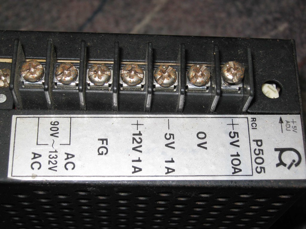
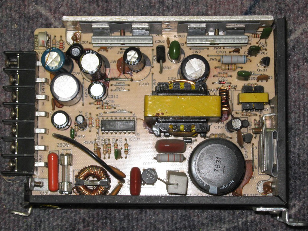
i openend it up, but there's no jumper / connector to change it to 240v (which doesn't mean i couldn't simply replace it by a 240v version)
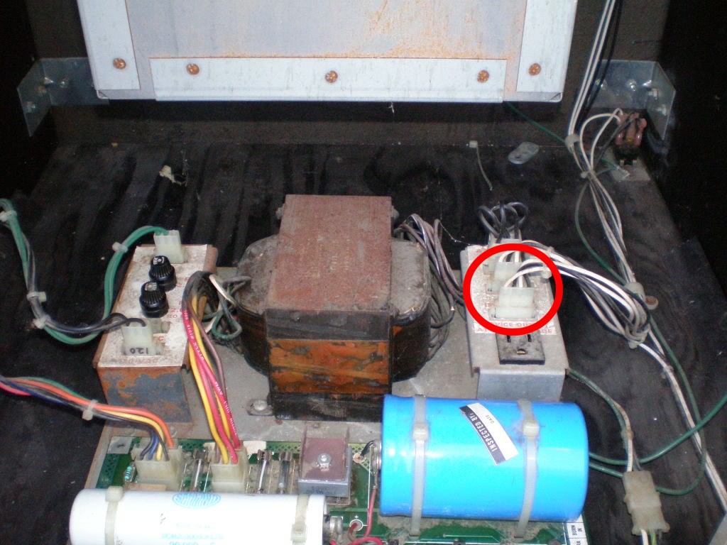
let's start at the very beginning, the point where the power "enters" the cabinet through the line filter (where i blew the varistor). note the black / white / green wires on the right
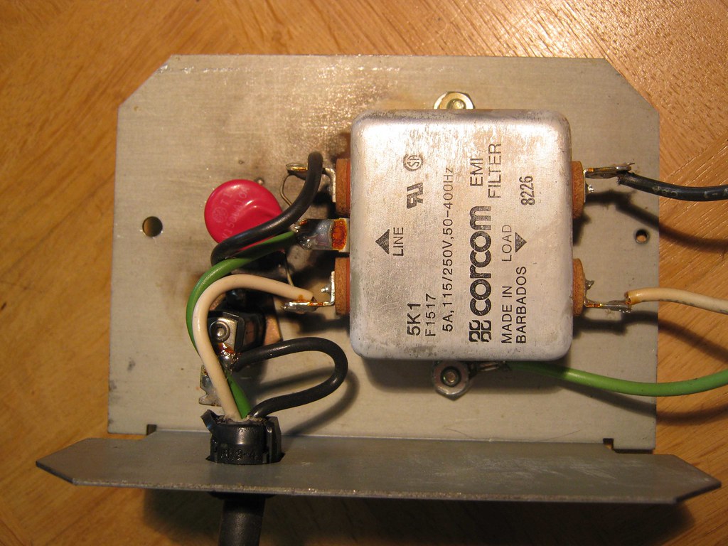
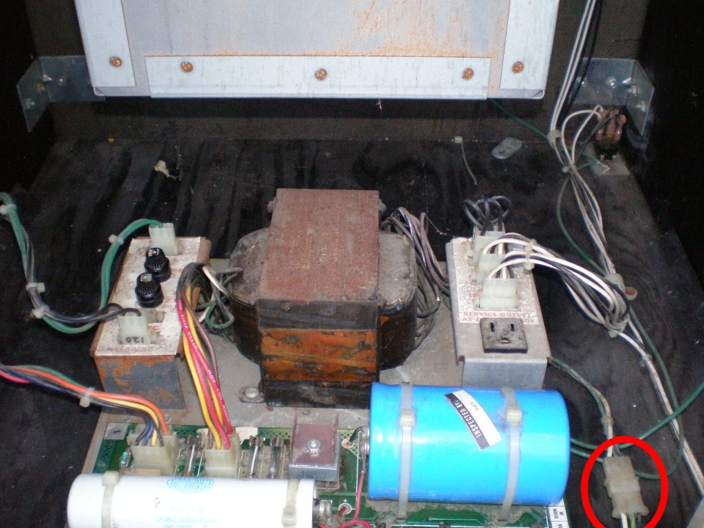
normally, those wires eventually go into the power supply (see original setup where i marked the appropriate connector)
alright, i'm missing power so far, let's go through all the wires / connectors of the harness(es) i have, starting with the one with two interlock switches and the on / off switch
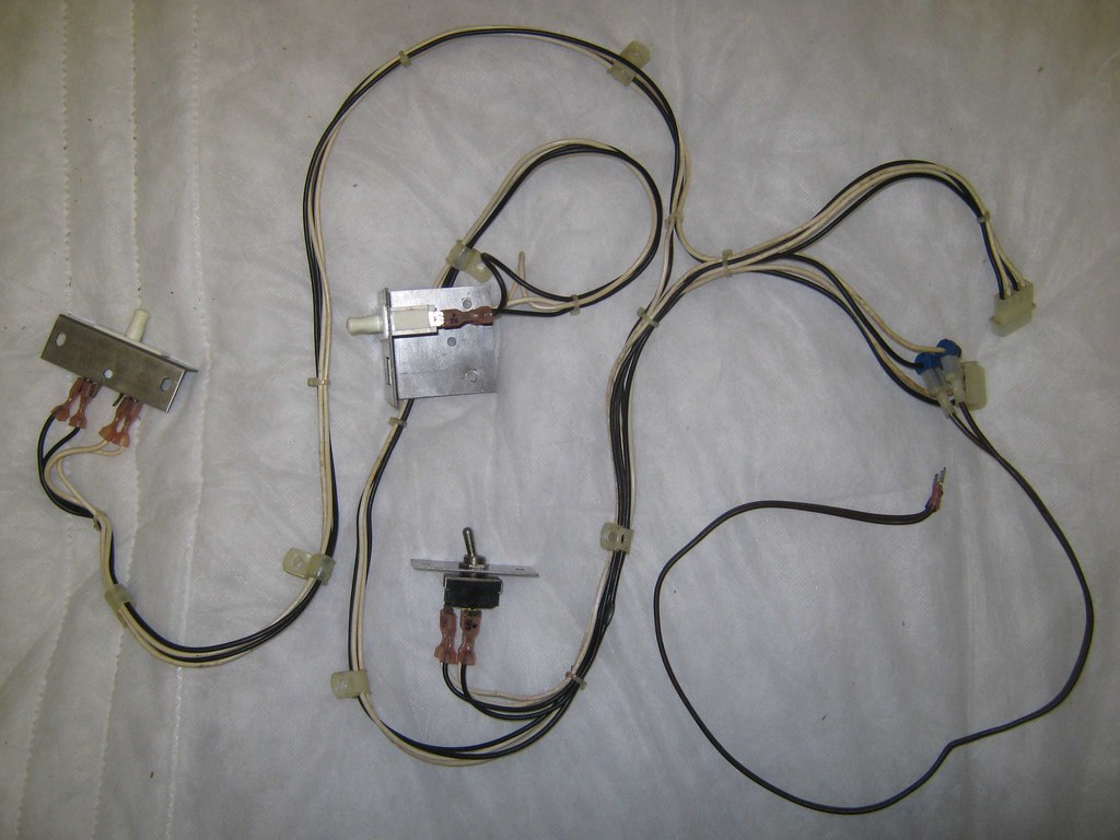
as you can see, someone has spliced in a brown wire with two connectors which have to be attached to the switching power supply, but where? 120v?
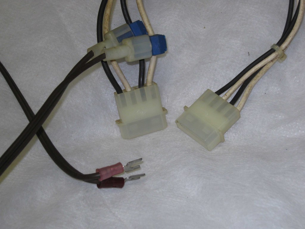
normally, without the spliced in brown wire, those two bigger white connectors go into the original power supply (you can see the on / off switch in the background)
up next, a part of the harness which causes no problems (yeah!!!), but i wanted to show it to you anway
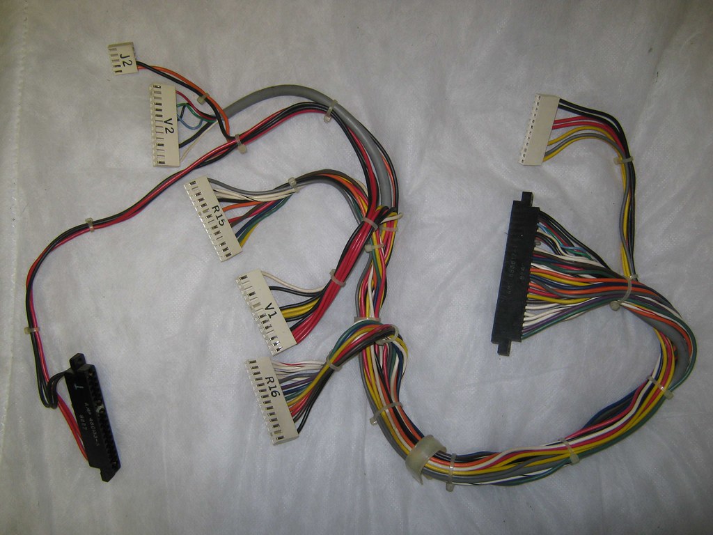
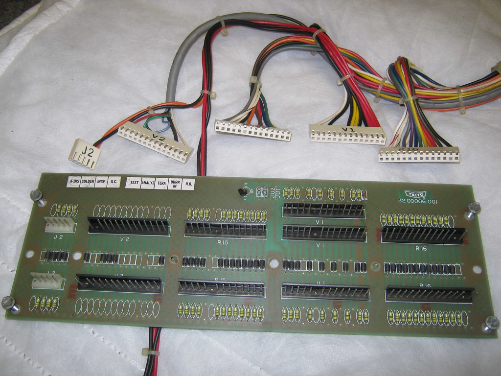
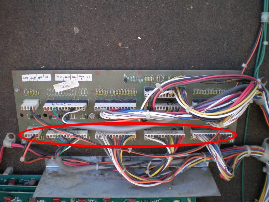
those five nicely labeled connectors slide into the lower row of the filter board
here's the original setup
now there are only three connectors left
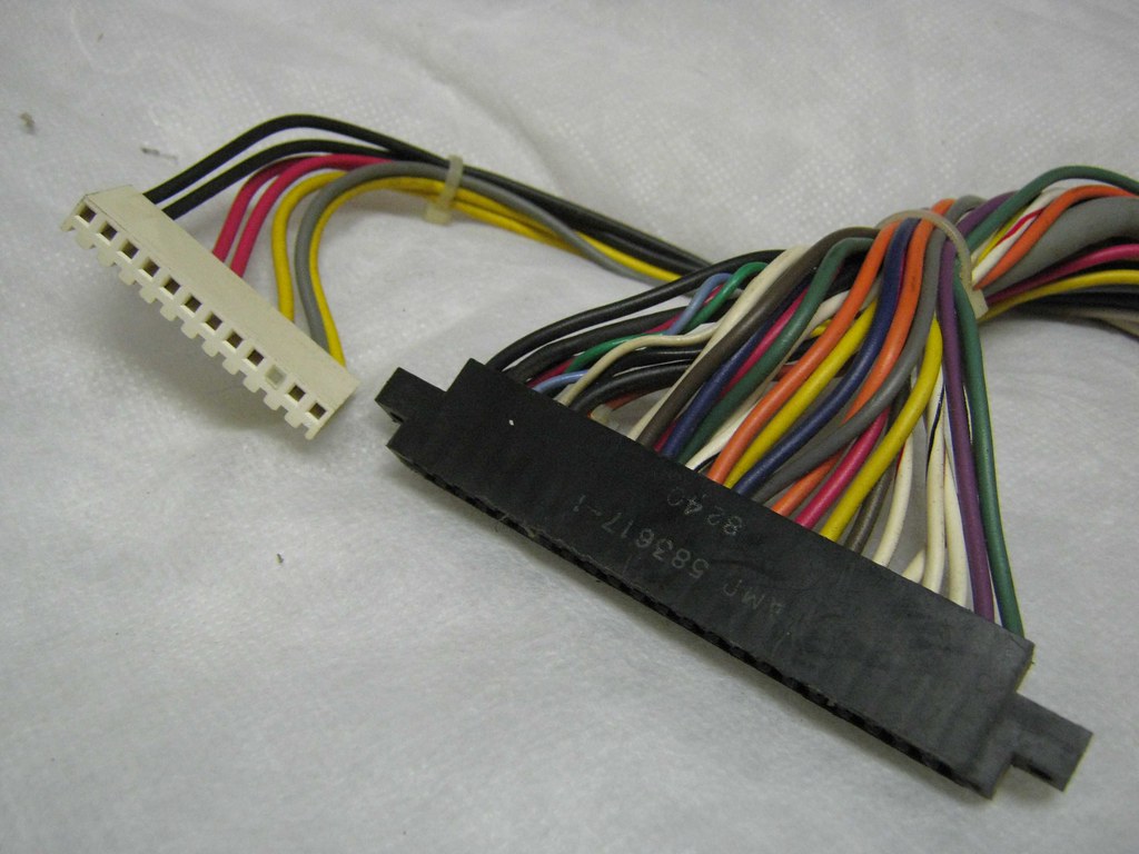
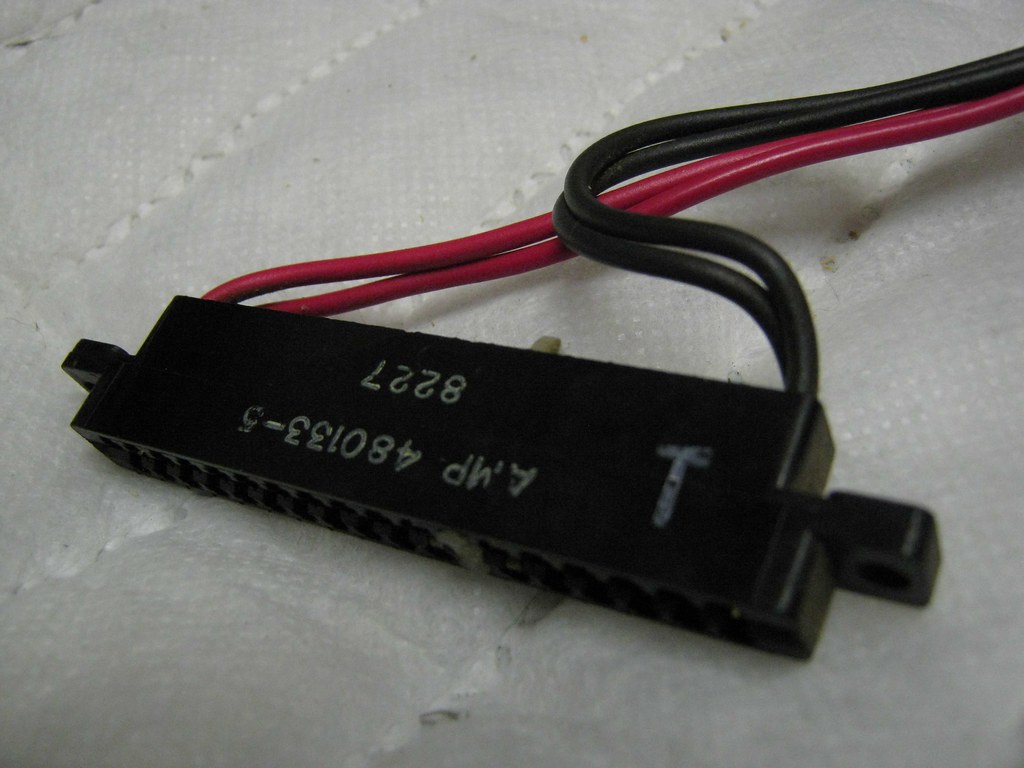
the same three connectors on the original pcb (one is not visible, but i've marked the wires to illustrate where it leads)
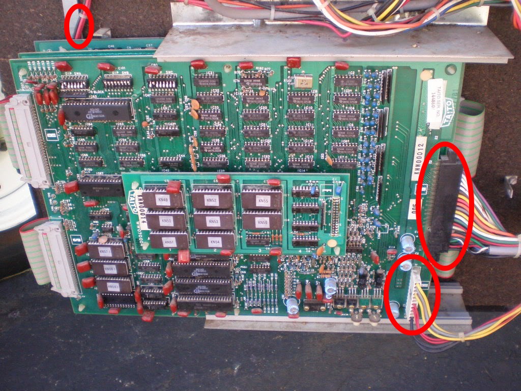
now it's starting to get complicated with
THIS 


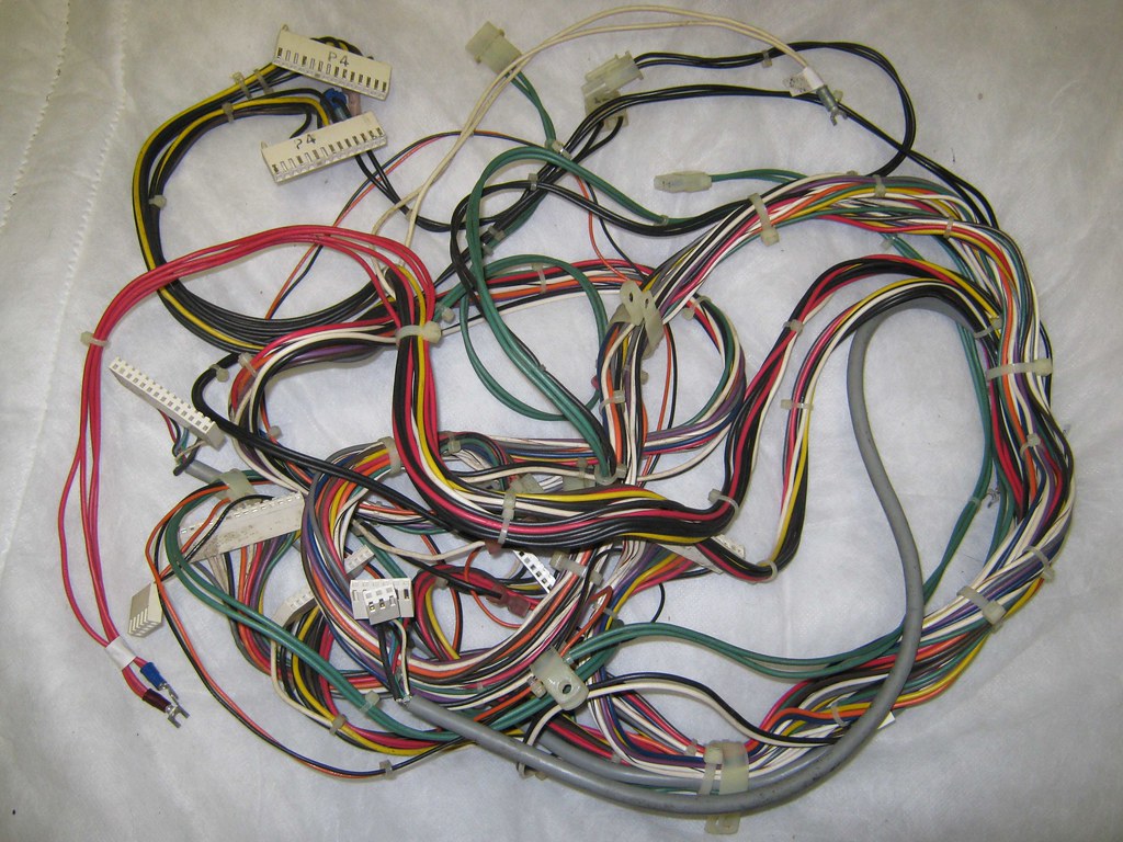
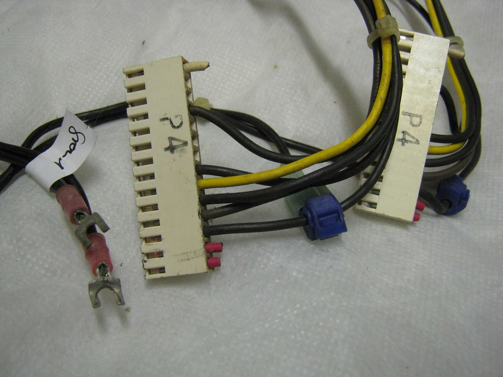
let's go through the wires / connectors individually, starting with two connectors labeled P4. as you can see, some of the wires have been cut and once again two new black wires have been spliced in (position 3 of the connectors). the manual says that the black wires on position 3 are GROUND, therefore the spliced in black wires will be connected to the switcher's GROUND, right? (note that i put the ground label on the wires there myself just to make sure i don't forget)
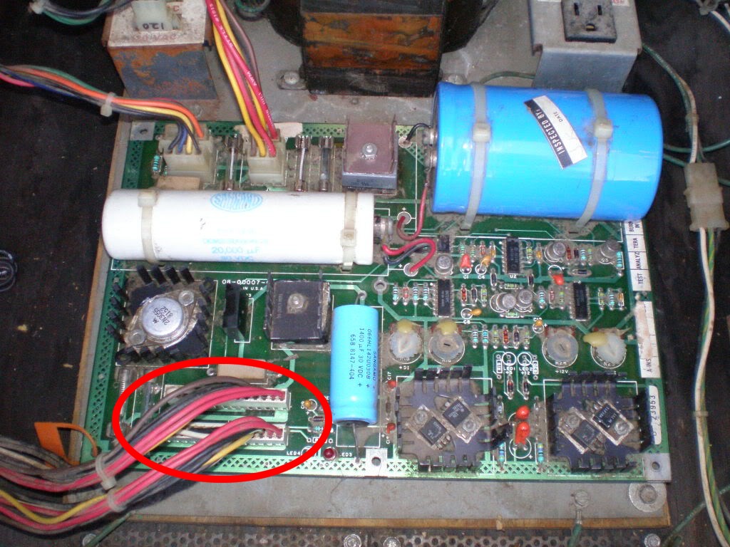
here's the original setup: the two P4 connectors connected to the original power supply
up next we have something called
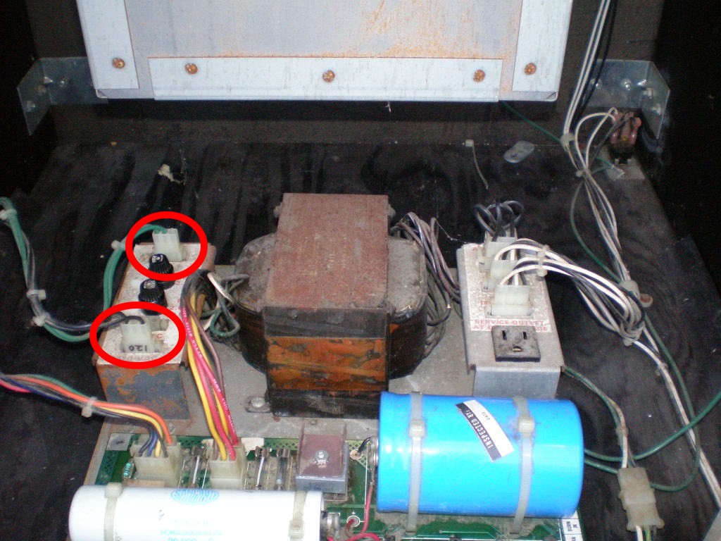
secondary bracket in the manual. two connectors / wires are coming out of it, one labeled 120 and the other one labeled 6.3 (in the manual listed as 120vac and 6.3vac). once again, here's the original setup

and here you can see those two connectors (on the right) on the harness, the black one ends in the connector on the left and this is supposed to power the monitor (with 120vac). however, i have
NO IDEA where / how to connect other of those two (120 & 6.3) connectors! i really don't!!!

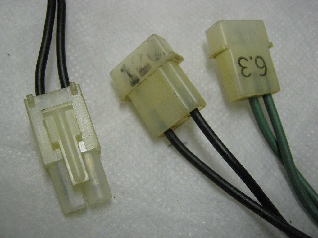
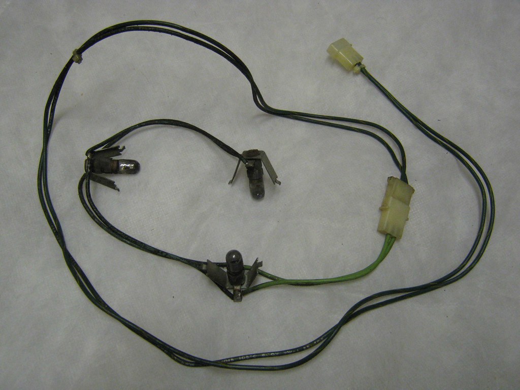
the 6.3 line ends in a green connector which eventually power the marquee lights and the instruction lights. question: are those really powered by alternating current? here's a picture of the instruction lights harness

now it gets a little bit easier (for a while): the following connectors all go to the upper part of the filter board. the wires with the grey coating at the bottom of the picture are the ones for the monitor
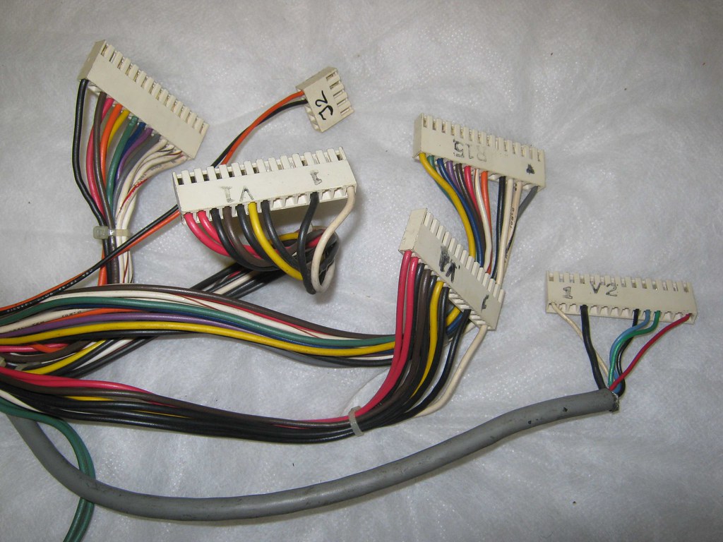
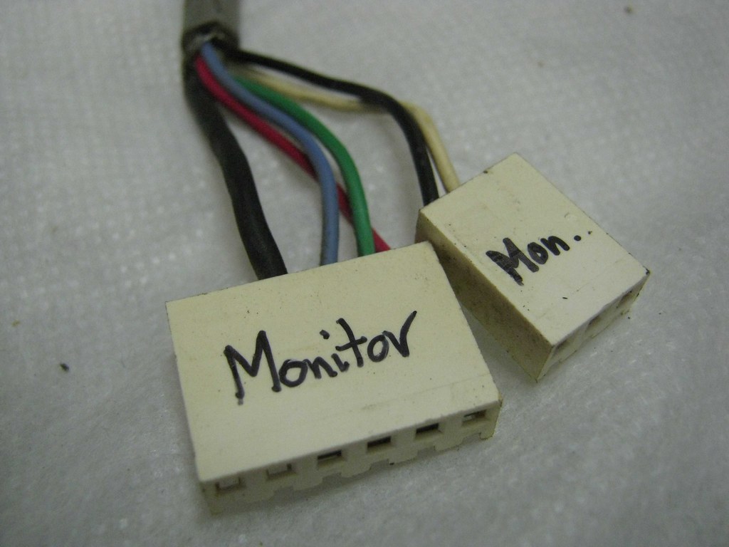
here's the other end of that grey line (labeled by moi)
the original monitor hook-up ...
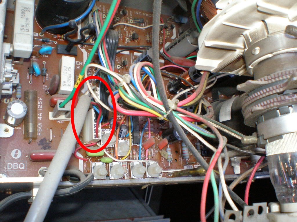
... plus the original filter board connections - no problems here!
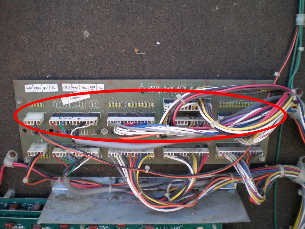
i'm afraid we have to look at those filter board connectors again. to be more specific, let's have a look at the two V1 connectors and especially at those red and white wires (i've circled them)
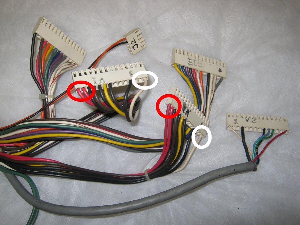
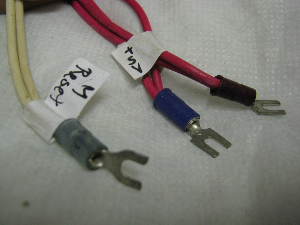
those wires end in "switcher connectors" again and the manual states the red wires as
+5V and the white wires as
M RESET. m reset? what the f*** is that? never heard before! where do i connect those to a switcher?
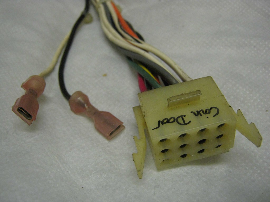
good news guys, we're almost done! but one mystery remains: very close to the filter board connectors there is a tiny connector with a black and a white wire
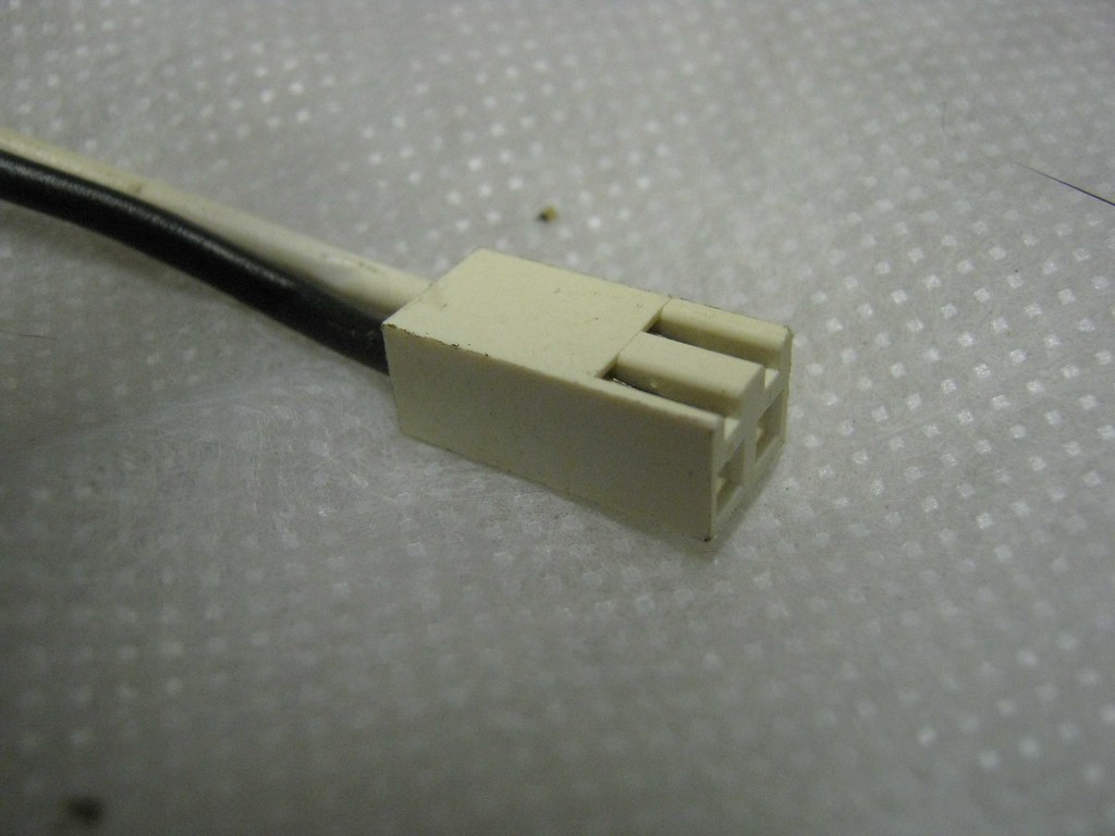
if you follow those wires, they end with the coin door connector, therefore i'm pretty sure those wires are there to power a coin counter. the problem is: where does that rectangular connector (the one pictured before) connect to? i couldn't find it on the internet pictures and there's no free space anywhere to connect it to! is it possible that it has to go somewhere on the main pcb because it's close to the filter board? (I don't have a board here yet, so i can't check)
one last thing: does anyone know where the following connector has to be attached to?

(man, if everything was that easy)
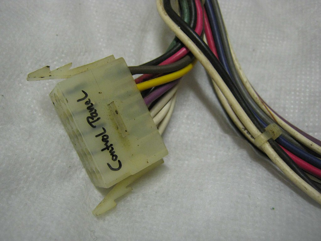
that's it guys, thx a lot for your patience to read all that stuff, i can't wait to read your replies and hear your input! if you need any more pictures, just say so ...